写在前面:
本文章为个人学习笔记,方便以后自己复习,也希望能帮助到他人。
由于本人水平有限难免出现错误,还请评论区指出,多多指教。
部分图元和素材来源于网络,如有侵权请联系本人删除。
参考资料与链接会在文章末尾贴出。
=======================================================================
1.Planar Mapping
我们知道我们可以利用模型的uv采样贴图,但是有些时候我们没有或不想用模型自带的uv,我们可以自己生成一套uv。所谓的Planar Mapping就是利用世界空间中顶点的位置来做uv。
如下面的代码例子,我们用世界空间顶点坐标的zy轴作为uv,相当与我们把贴图在模型的侧面粘上去;如果是xz则是在顶部;xy则是在正面,可以自行脑补三维空间或画图理解。
       v2f vert (a2v v)
            {
                v2f o;
                o.pos = UnityObjectToClipPos(v.pos);
                float4 worldPos = mul(unity_ObjectToWorld,v.pos);
                /*
                    actually we just project the texture on the top of the model(xz),or front(xy),side(zy)
                */
                o.uv = TRANSFORM_TEX(worldPos.zy, _MainTex);
                return o;
            }

            float4 frag (v2f i) : SV_Target
            {
                //float2 uv = normalize(i.uv);
                float4 finalCol = tex2D(_MainTex,i.uv);
                return finalCol;
            }
效果:
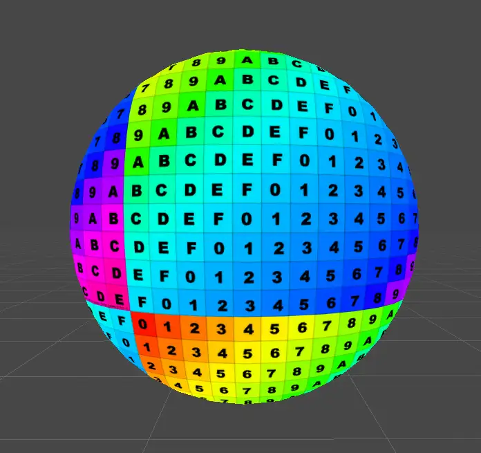
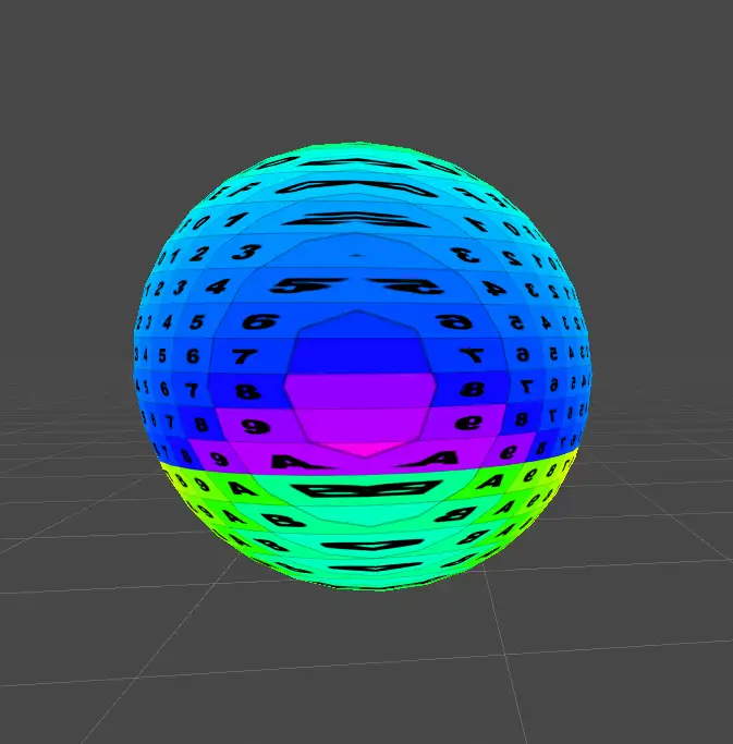
缺点就是除了该面之外,其他面会有拉伸和形变,因此应用最多是在一些不那么立体的模型上:
2.Triplanar Mapping
因为Planar Mapping有局限,因此我们引入Triplanar Mapping,简单来说,我们分别再xyz三个轴都做一次纹理采样后,再把结果“贴”到对应的轴上。
这次我们的v2f结构中需要三样东西:
       struct v2f
            {
                float4 pos : SV_POSITION;
                float3 normal : TEXCOORD0;
                float3 posWS : TEXCOORD1;
            };
依旧用posWS作为uv采样贴图,而normal则用来做为权重。
在fragShader中,先计算三个方向的uv然后从三个方向采样贴图:
         // calculate UV coordinates for three projection
                float2 uv_front = TRANSFORM_TEX(i.posWS.xy,_MainTex);
                float2 uv_side = TRANSFORM_TEX(i.posWS.zy,_MainTex);
                float2 uv_top = TRANSFORM_TEX(i.posWS.xz,_MainTex);

                // sample 3 times using different uv for different direction(front side top)
                float4 tex_front = tex2D(_MainTex,uv_front);
                float4 tex_side = tex2D(_MainTex,uv_side);
                float4 tex_top = tex2D(_MainTex,uv_top);
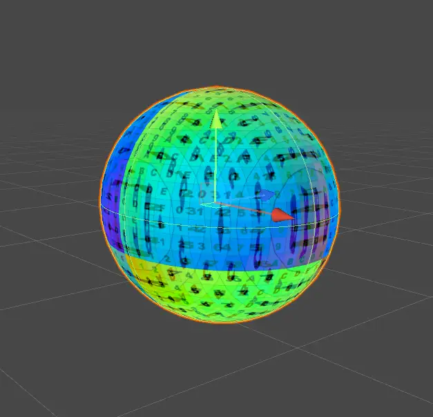
先把结果加起来输出一下看看,记得结果要除3,不然会太亮:
尽管也会有拉伸,但看起来比Planar Mapping要好一点。
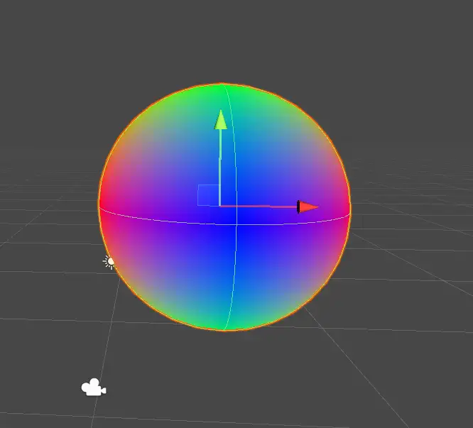
接下来继续改进,我们希望(比如正面)采样后的结果就只贴在正面,更准确地说采样结果对除正面外的地方影响小一点(最理想就是没影响)。因此我们用模型在世界空间中的法线作为权重,与对应结果相乘。注意:法线表示方向有正负,而作为权重我们可以取期绝对值。
          // now we use normal of model as weight for different direction
                float3 weight = i.normal;
                // make sure value of weight is positive
                weight = abs(weight);
                return float4(weight,1);
输出法线看看:
          tex_front *= weight.z;
                tex_side *= weight.x;
                tex_top *= weight.y;

                float4 finalCol = tex_front + tex_side + tex_top;
                return finalCol;
输出结果:
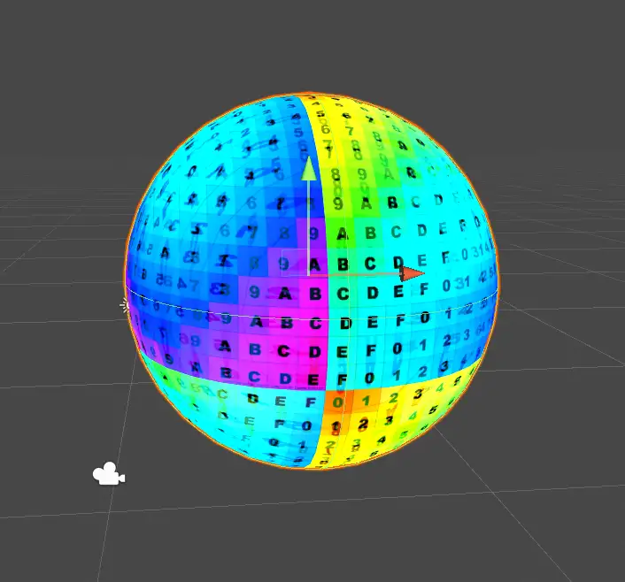
比想象中要亮,查看上述代码,其实就是没有像第一次输出一样除3,结果叠加超出了合理范围。但是我们这里不要简单把结果除3,我们可以调整权重。
ps:如果一开始难以理解某些某些数学公式的操作是正常的,个人建议可以试下代入几个特殊值尝试理解公式到底做了什么。比如一个(1,0.5,0)的向量调整前调整后计算结果有什么不同。
          // make it so the sum of all components is 1, or the output will be brighter than we expected
                weight = weight/(weight.x + weight.y + weight.z);
                // multiply col with its weight
                tex_front *= weight.z;
                tex_side *= weight.x;
                tex_top *= weight.y;

                float4 finalCol = tex_front + tex_side + tex_top;
                return finalCol;
现在看起来正常一点。
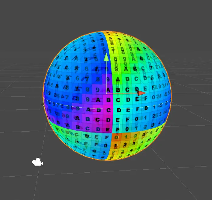
我们可以继续调整一下面与面(即不同轴,不同方向)的过渡效果,现在是比较模糊,自然?在某些情况下自然模糊过渡确实是我们想要的。但是这里我们可以设置一个参数控制过渡是模糊还是边界分明。开放一个叫sharpness的参数做幂运算控制过渡效果:
注意pow的位置!不然效果不一样
        //_Sharpness("Sharpness",Range(1,64)) = 1
             float4 frag (v2f i) : SV_Target
            {
                // calculate UV coordinates for three projection
                float2 uv_front = TRANSFORM_TEX(i.posWS.xy,_MainTex);
                float2 uv_side = TRANSFORM_TEX(i.posWS.zy,_MainTex);
                float2 uv_top = TRANSFORM_TEX(i.posWS.xz,_MainTex);

                // sample 3 times using different uv for different direction(front side top)
                float4 tex_front = tex2D(_MainTex,uv_front);
                float4 tex_side = tex2D(_MainTex,uv_side);
                float4 tex_top = tex2D(_MainTex,uv_top);
                // now we use normal of model as weight for different direction
                float3 weight = i.normal;
                // make sure value of weight is positive
                weight = abs(weight);
                //return float4(weight,1);
                // control the transition of boundaries smoother or sharper
                weight = pow(weight,_Sharpness);
                // make it so the sum of all components is 1, or the output will be brighter than we expected
                weight = weight/(weight.x + weight.y + weight.z);
                // multiply col with its weight
                tex_front *= weight.z;
                tex_side *= weight.x;
                tex_top *= weight.y;

                float4 finalCol = tex_front + tex_side + tex_top;
                return finalCol;
            }
输出weight看下:
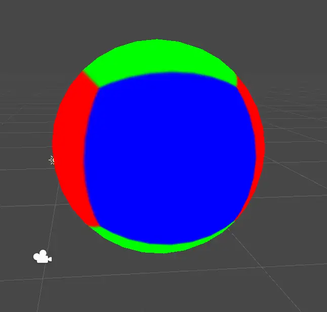
最终结果:
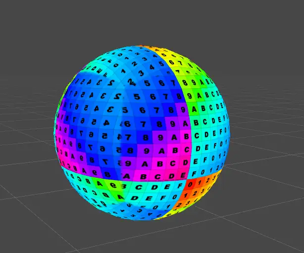
可以看到边缘过渡很实。
我们甚至可以对于不同的面应用不同的纹理,比如top是草地,side和front是岩石。
参考资料:
标签:Planar,weight,uv,Mapping,tex,float4,front,side,Triplanar From: https://www.cnblogs.com/pisconoob/p/16847840.html