dielectric
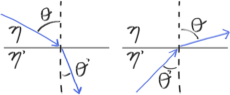
水、玻璃、钻石等透明材料都是电介质。当光线照射到它们身上时,它会分裂成反射光线和折射(透射)光线。我们将通过在反射和折射之间随机选择来处理这个问题,每次相互作用只产生一个散射射线。
折射程度 : 是根据两个介质折射率的差值决定的。
Refraction
Snell's Law
$$
\eta \cdot \sin{\theta} = {\eta}' \cdot \sin{{\theta}'}
$$
$$
\sin{{\theta}'} = \frac{\eta}{{\eta}'} \sin{\theta}
$$
折射光线 ${R}'$ ,折射表面的法线 ${n}'$ 折射对应的折射角 $\theta'$ 我们将 $R'$ 分解为和 $n'$ 垂直和平行的
$$
R' = R'{\perp} + R'
$$
$$
R'_{\perp} = \frac{\eta}{\eta'}(R+\cos{\theta}n)
$$
$$
R'{\parallel} = - \sqrt{ 1 - \left| R' \right|^2 }n
$$
$\cos{\theta}$ 可以通过点乘得到。
$$
R'_{\perp} = \frac{\eta}{\eta'}(R+ (-R \cdot n) n)
$$
inline vec3 refract(const vec3& uv, const vec3& n, double etai_over_etat) {
    auto cos_theta = fmin(dot(-uv, n), 1.0);
    vec3 r_out_perp =  etai_over_etat * (uv + cos_theta*n);
    vec3 r_out_parallel = -sqrt(fabs(1.0 - r_out_perp.length_squared())) * n;
    return r_out_perp + r_out_parallel;
}
the dieliectric class
class dielectric : public material {
  public:
    dielectric(double refraction_index) : refraction_index(refraction_index) {}

    bool scatter(const ray& r_in, const hit_record& rec, color& attenuation, ray& scattered)
    const override {
        attenuation = color(1.0, 1.0, 1.0);
        double ri = rec.front_face ? (1.0/refraction_index) : refraction_index;

        vec3 unit_direction = unit_vector(r_in.direction());
        vec3 refracted = refract(unit_direction, rec.normal, ri);

        scattered = ray(rec.p, refracted);
        return true;
    }

  private:
    // Refractive index in vacuum or air, or the ratio of the material's refractive index over
    // the refractive index of the enclosing media
    double refraction_index;
};
全反射
有一些光线角无法用斯涅尔定律求解。当光线以足够的掠射角进入折射率较低的介质时它能以大于90度的角度折射.
如果
$$
\sin{{\theta}'} = \frac{1.5}{1.0} \sin{\theta} >0
$$
因此 角度 会出现问题。所以我们要判断一下是否能够反射
double cos_theta = fmin(dot(-unit_direction, rec.normal), 1.0);
double sin_theta = sqrt(1.0 - cos_theta*cos_theta);

if (ri * sin_theta > 1.0) {
    // Must Reflect
    ...
} else {
    // Can Refract
    ...
}
这里所有的光都被反射,因为在实践中,这通常是在固体物体内部,所以它被称为全内反射。这就是为什么有时候当你在水下时,水与空气的边界就像一面完美的镜子如果你在水下向上看,你可以看到水面上的东西,但是当你靠近水面侧身看时,水面看起来就像一面镜子。
class dielectric : public material {
  public:
    dielectric(double refraction_index) : refraction_index(refraction_index) {}

    bool scatter(const ray& r_in, const hit_record& rec, color& attenuation, ray& scattered)
    const override {
        attenuation = color(1.0, 1.0, 1.0);
        double ri = rec.front_face ? (1.0/refraction_index) : refraction_index;

        vec3 unit_direction = unit_vector(r_in.direction());
        double cos_theta = fmin(dot(-unit_direction, rec.normal), 1.0);
        double sin_theta = sqrt(1.0 - cos_theta*cos_theta);

        bool cannot_refract = ri * sin_theta > 1.0;
        vec3 direction;

        if (cannot_refract)
            direction = reflect(unit_direction, rec.normal);
        else
            direction = refract(unit_direction, rec.normal, ri);

        scattered = ray(rec.p, direction);
        return true;
    }

  private:
    // Refractive index in vacuum or air, or the ratio of the material's refractive index over
    // the refractive index of the enclosing media
    double refraction_index;
};
Attenuation is always 1 — the glass surface absorbs nothing.
事实证明,给定一个折射率大于空气的材料球体,没有任何入射角能产生完全的内反射无论是在射线球体的入口还是在射线球体的出口。这是由于球体的几何形状,因为入射光线总是弯曲到一个较小的角度,然后在出口时弯曲回原来的角度。
那么我们如何说明全内反射呢?如果球体的折射率小于它所处的介质,那么我们就可以用浅掠角撞击它,得到全外反射。这应该足以观察到效果。
我们将模拟一个充满水的世界(折射率约为1.33),并将球体材料更改为空气(折射率1.00)一个气泡!要做到这一点,改变左边球体材料的折射率为
auto material_ground = make_shared<lambertian>(color(0.8, 0.8, 0.0));
auto material_center = make_shared<lambertian>(color(0.1, 0.2, 0.5));
auto material_left   = make_shared<dielectric>(1.00 / 1.33);
auto material_right  = make_shared<metal>(color(0.8, 0.6, 0.2), 1.0);
Schlick 近似
用克里斯托弗·施里克(Christophe Schlick)的一个便宜而惊人准确的多项式近似。这就产生了我们的全玻璃材料
让我们建造一个空心玻璃球。这是一个厚度的球体,内部有另一个空气。如果您想到射线穿过这样的物体的路径,它将击中外部球体,折射,击中内部球(假设我们确实击中了它),第二次折射,然后穿过内部的空气。然后,它将继续前进,击中内部球体的内部表面,向后折射,然后击中外部球体的内表面,最后折射并退回到场景大气中。
外球只是用标准玻璃球对其进行建模,其折射率约为1.50(将外部空气从外部空气中建模为玻璃)。内部球体有些不同,因为其折射率应相对于周围外球的物质,从而建模从玻璃向内空气的过渡。这实际上很容易指定,因为Refraction_Index参数与介电材料可以解释为对象的折射率的比率除以封闭介质的折射率。在这种情况下,内部球体将在玻璃的折射率(封闭介质)或1.00/1.50 = 0.67上具有空气(内部球体材料)的折射率(内部球体材料)或者 0.67
auto material_ground = make_shared<lambertian>(color(0.8, 0.8, 0.0));
auto material_center = make_shared<lambertian>(color(0.1, 0.2, 0.5));
auto material_left   = make_shared<dielectric>(1.50);
auto material_bubble = make_shared<dielectric>(1.00 / 1.50);
auto material_right  = make_shared<metal>(color(0.8, 0.6, 0.2), 0.0);

world.add(make_shared<sphere>(point3( 0.0, -100.5, -1.0), 100.0, material_ground));
world.add(make_shared<sphere>(point3( 0.0,    0.0, -1.2),   0.5, material_center));
world.add(make_shared<sphere>(point3(-1.0,    0.0, -1.0),   0.5, material_left));
world.add(make_shared<sphere>(point3(-1.0,    0.0, -1.0),   0.4, material_bubble));
world.add(make_shared<sphere>(point3( 1.0,    0.0, -1.0),   0.5, material_right));
可移动摄像头
光线总 origin 出发,指向 -z,同时 z = -2 就是平面
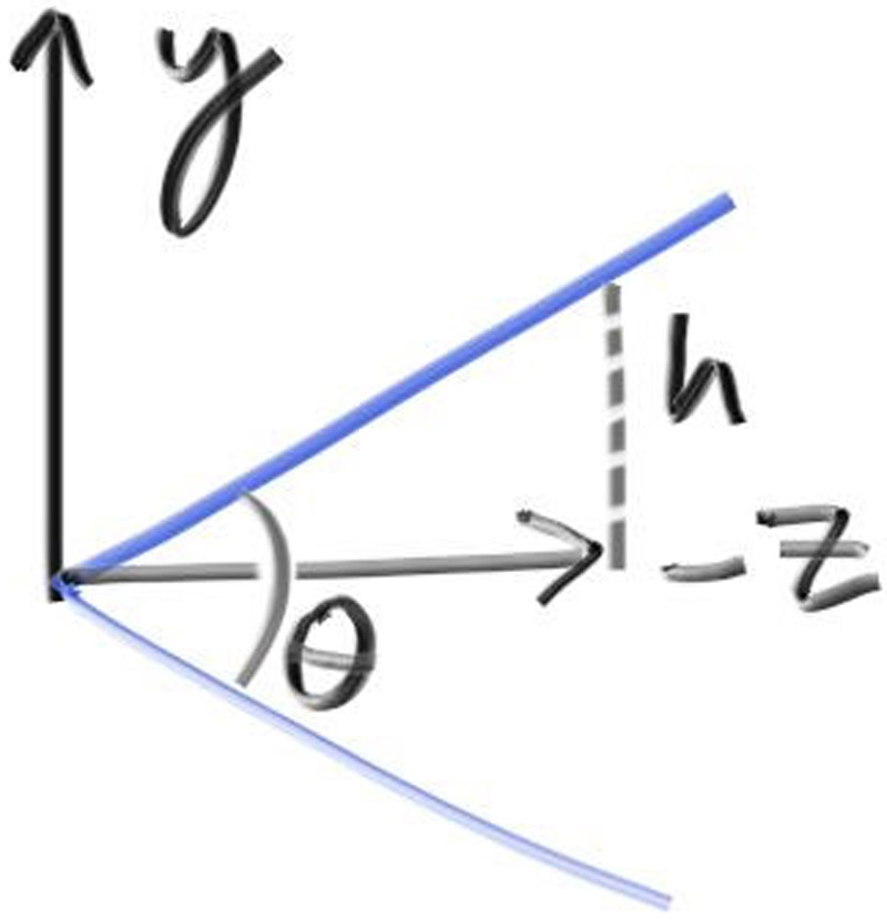
$h = \tan{\frac{\theta}{2}}$
class camera {
  public:
    double aspect_ratio      = 1.0;  // Ratio of image width over height
    int    image_width       = 100;  // Rendered image width in pixel count
    int    samples_per_pixel = 10;   // Count of random samples for each pixel
    int    max_depth         = 10;   // Maximum number of ray bounces into scene

    double vfov = 90;  // Vertical view angle (field of view)

    void render(const hittable& world) {
    ...

  private:
    ...

    void initialize() {
        image_height = int(image_width / aspect_ratio);
        image_height = (image_height < 1) ? 1 : image_height;

        pixel_samples_scale = 1.0 / samples_per_pixel;

        center = point3(0, 0, 0);

        // Determine viewport dimensions.
        auto focal_length = 1.0;
        auto theta = degrees_to_radians(vfov);
        auto h = tan(theta/2);
        auto viewport_height = 2 * h * focal_length;
        auto viewport_width = viewport_height * (double(image_width)/image_height);

        // Calculate the vectors across the horizontal and down the vertical viewport edges.
        auto viewport_u = vec3(viewport_width, 0, 0);
        auto viewport_v = vec3(0, -viewport_height, 0);

        // Calculate the horizontal and vertical delta vectors from pixel to pixel.
        pixel_delta_u = viewport_u / image_width;
        pixel_delta_v = viewport_v / image_height;

        // Calculate the location of the upper left pixel.
        auto viewport_upper_left =
            center - vec3(0, 0, focal_length) - viewport_u/2 - viewport_v/2;
        pixel00_loc = viewport_upper_left + 0.5 * (pixel_delta_u + pixel_delta_v);
    }

    ...
};
int main() {
    hittable_list world;

    auto R = cos(pi/4);

    auto material_left  = make_shared<lambertian>(color(0,0,1));
    auto material_right = make_shared<lambertian>(color(1,0,0));

    world.add(make_shared<sphere>(point3(-R, 0, -1), R, material_left));
    world.add(make_shared<sphere>(point3( R, 0, -1), R, material_right));

    camera cam;

    cam.aspect_ratio      = 16.0 / 9.0;
    cam.image_width       = 400;
    cam.samples_per_pixel = 100;
    cam.max_depth         = 50;

    cam.vfov = 90;

    cam.render(world);
}
定位相机
相机位置 : lookfrom , look at: lookat
我们还需要一种方法来指定相机的滚动或侧向倾斜:围绕look -look - from轴的旋转。另一种思考方式是,即使你一直不停地看,你仍然可以在鼻子周围旋转你的头。我们需要的是一种为相机指定向上矢量的方法。
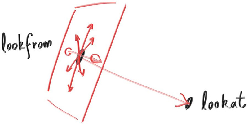
我们可以指定任何向上的向量,只要它不平行于视图方向。将此向上向量投影到与视图方向正交的平面上,以获得与相机相关的向上向量。我使用将其命名为视图向上(vup)向量的通用约定。经过一些叉乘和向量归一化之后,我们现在有了一个完整的标准正交基 $(u,v,w)$ 用来描述相机的方向。
- u : 单位向量, point to right
- v : 单位向量, point to up
- w :单位向量,指向与视野方向相反的方向

class camera {
  public:
    double aspect_ratio      = 1.0;  // Ratio of image width over height
    int    image_width       = 100;  // Rendered image width in pixel count
    int    samples_per_pixel = 10;   // Count of random samples for each pixel
    int    max_depth         = 10;   // Maximum number of ray bounces into scene

    double vfov     = 90;              // Vertical view angle (field of view)
    point3 lookfrom = point3(0,0,0);   // Point camera is looking from
    point3 lookat   = point3(0,0,-1);  // Point camera is looking at
    vec3   vup      = vec3(0,1,0);     // Camera-relative "up" direction

    ...

  private:
    int    image_height;         // Rendered image height
    double pixel_samples_scale;  // Color scale factor for a sum of pixel samples
    point3 center;               // Camera center
    point3 pixel00_loc;          // Location of pixel 0, 0
    vec3   pixel_delta_u;        // Offset to pixel to the right
    vec3   pixel_delta_v;        // Offset to pixel below
    vec3   u, v, w;              // Camera frame basis vectors

    void initialize() {
        image_height = int(image_width / aspect_ratio);
        image_height = (image_height < 1) ? 1 : image_height;

        pixel_samples_scale = 1.0 / samples_per_pixel;

        center = lookfrom;

        // Determine viewport dimensions.
        auto focal_length = (lookfrom - lookat).length();
        auto theta = degrees_to_radians(vfov);
        auto h = tan(theta/2);
        auto viewport_height = 2 * h * focal_length;
        auto viewport_width = viewport_height * (double(image_width)/image_height);

        // Calculate the u,v,w unit basis vectors for the camera coordinate frame.
        w = unit_vector(lookfrom - lookat);
        u = unit_vector(cross(vup, w));
        v = cross(w, u);

        // Calculate the vectors across the horizontal and down the vertical viewport edges.
        vec3 viewport_u = viewport_width * u;    // Vector across viewport horizontal edge
        vec3 viewport_v = viewport_height * -v;  // Vector down viewport vertical edge

        // Calculate the horizontal and vertical delta vectors from pixel to pixel.
        pixel_delta_u = viewport_u / image_width;
        pixel_delta_v = viewport_v / image_height;

        // Calculate the location of the upper left pixel.
        auto viewport_upper_left = center - (focal_length * w) - viewport_u/2 - viewport_v/2;
        pixel00_loc = viewport_upper_left + 0.5 * (pixel_delta_u + pixel_delta_v);
    }

    ...

  private:
};
散焦模糊
现在我们的最后一个功能:散焦模糊。注意,摄影师称之为景深,所以一定要在你的光线追踪朋友中只使用术语散焦模糊。
我们在真实相机中出现散焦模糊的原因是,它们需要一个大洞(而不仅仅是针孔)来收集光线。一个大洞会使所有东西散焦,但如果我们把镜头放在胶片/传感器前面,就会有一定的距离使所有东西都聚焦。放置在该距离处的对象将显示在焦点上,并且距离该距离越远,它们将线性地显示得越模糊。你可以这样想透镜:所有来自焦距处特定点的光线——以及照射到透镜上的光线——都会向后弯曲到图像传感器上的一个点。
我们把相机中心到物体完全对焦的平面之间的距离称为焦距。请注意,焦距通常与焦距不同,焦距是相机中心和图像平面之间的距离。然而,对于我们的模型,这两个将具有相同的值,因为我们将像素网格放在焦平面上,焦平面是离相机中心的焦距。
在物理相机中,焦距由镜头和胶片/传感器之间的距离控制。这就是为什么当你改变焦点时,你会看到镜头相对于相机移动(这也可能发生在你的手机相机中,但传感器会移动)。“光圈”是一个孔,用来有效地控制镜头的大小。对于真正的相机,如果你需要更多的光,你会使光圈更大,并且远离焦距的物体会变得更模糊。对于我们的虚拟相机,我们可以有一个完美的传感器,而且永远不需要更多的光,所以我们只在需要散焦模糊时使用光圈。
薄透镜近似
对于我们的代码,我们可以模拟顺序:传感器,然后镜头,然后光圈。然后我们就可以计算出光线的发送位置,并在计算后翻转图像(图像在胶片上倒过来投影)。然而,图形人员通常使用薄透镜近似
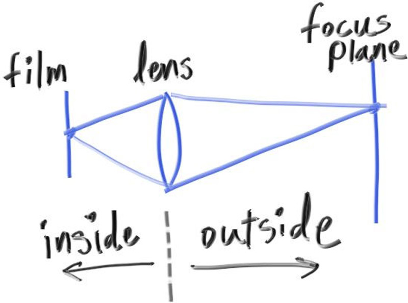
我们不需要为了渲染相机外部的图像而模拟相机内部的任何东西,那将是不必要的复杂性。相反,我通常从一个无限薄的圆形镜头开始光线,并将它们发送到焦平面上感兴趣的像素(距镜头的焦距),在3D世界中,该平面上的所有东西都是完美聚焦的。
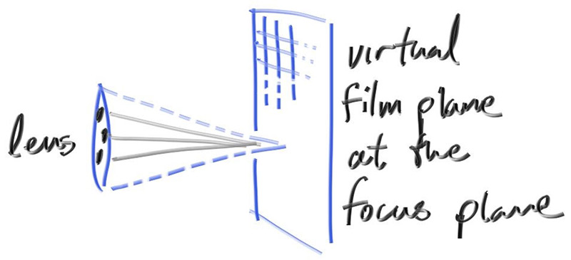
在实践中,我们通过将视口放置在这个平面中来实现这一点。把所有东西放在一起
- 聚焦平面与相机视角方向垂直
- 聚焦距离是相机中心到聚焦平面之间的距离。
- 视口位于聚焦平面上,以相机视图方向矢量为中心。
- 像素位置的网格位于视口中(位于3D世界中)。
- 从当前像素位置周围的区域中选择随机图像样本位置。
- 相机从镜头上的随机点发射光线,穿过当前图像样本位置。
没有散焦模糊,所有场景光线都来自相机中心(或从)。为了实现离焦模糊,我们在相机中心构造了一个圆盘。半径越大,散焦模糊越大。你可以想象我们的原始相机有一个半径为零的离焦磁盘(没有模糊),所以所有的光线都来自磁盘中心(从上看)。
那么,散磁盘应该多大?由于此磁盘的大小控制了我们得到多少散焦模糊,因此应该是相机类的参数。我们可以将磁盘的半径作为摄像机参数,但模糊会根据投影距离而有所不同。一个稍微更容易的参数是在摄像头中心指定视口中心和基座(Defocus磁盘)的锥角度的角度。当您改变给定镜头的重点距离时,这应该为您提供更一致的结果。
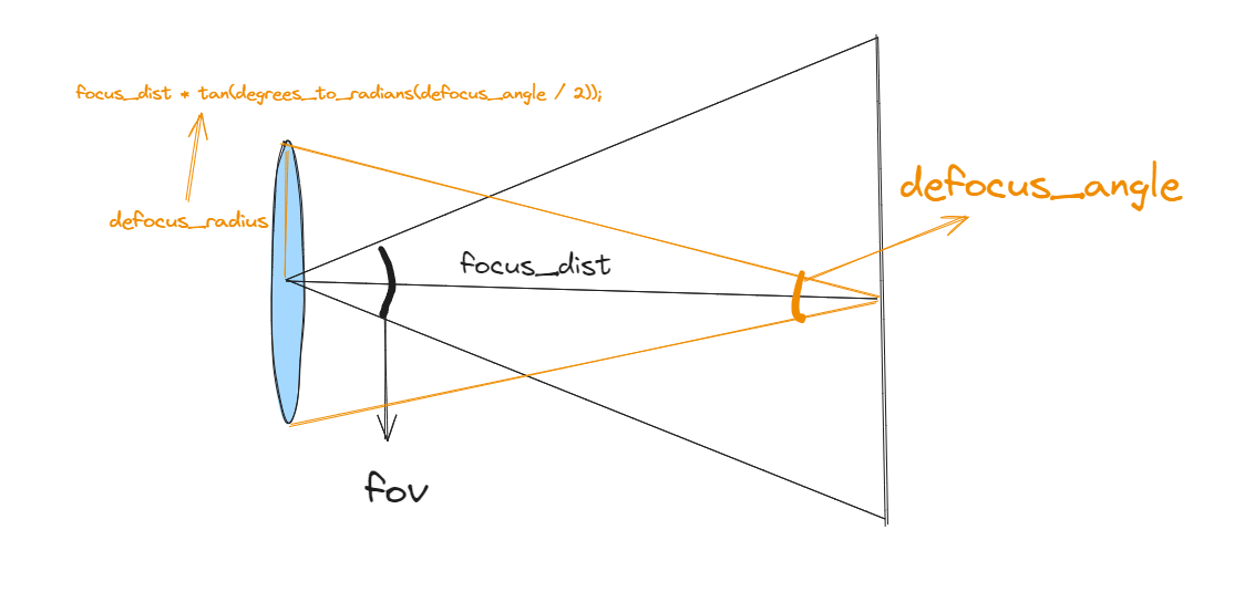
...

inline vec3 unit_vector(const vec3& u) {
    return v / v.length();
}

// 仅仅是二维的
inline vec3 random_in_unit_disk() {
    while (true) {
        auto p = vec3(random_double(-1,1), random_double(-1,1), 0);
        if (p.length_squared() < 1)
            return p;
    }
}

...
lass camera {
  public:
    double aspect_ratio      = 1.0;  // Ratio of image width over height
    int    image_width       = 100;  // Rendered image width in pixel count
    int    samples_per_pixel = 10;   // Count of random samples for each pixel
    int    max_depth         = 10;   // Maximum number of ray bounces into scene

    double vfov     = 90;              // Vertical view angle (field of view)
    point3 lookfrom = point3(0,0,0);   // Point camera is looking from
    point3 lookat   = point3(0,0,-1);  // Point camera is looking at
    vec3   vup      = vec3(0,1,0);     // Camera-relative "up" direction

    double defocus_angle = 0;  // Variation angle of rays through each pixel
    double focus_dist = 10;    // Distance from camera lookfrom point to plane of perfect focus

    ...

  private:
    int    image_height;         // Rendered image height
    double pixel_samples_scale;  // Color scale factor for a sum of pixel samples
    point3 center;               // Camera center
    point3 pixel00_loc;          // Location of pixel 0, 0
    vec3   pixel_delta_u;        // Offset to pixel to the right
    vec3   pixel_delta_v;        // Offset to pixel below
    vec3   u, v, w;              // Camera frame basis vectors
    vec3   defocus_disk_u;       // Defocus disk horizontal radius
    vec3   defocus_disk_v;       // Defocus disk vertical radius

    void initialize() {
        image_height = int(image_width / aspect_ratio);
        image_height = (image_height < 1) ? 1 : image_height;

        pixel_samples_scale = 1.0 / samples_per_pixel;

        center = lookfrom;

        // Determine viewport dimensions.
        auto focal_length = (lookfrom - lookat).length();
        auto theta = degrees_to_radians(vfov);
        auto h = tan(theta/2);
        auto viewport_height = 2 * h * focus_dist;
        auto viewport_width = viewport_height * (double(image_width)/image_height);

        // Calculate the u,v,w unit basis vectors for the camera coordinate frame.
        w = unit_vector(lookfrom - lookat);
        u = unit_vector(cross(vup, w));
        v = cross(w, u);

        // Calculate the vectors across the horizontal and down the vertical viewport edges.
        vec3 viewport_u = viewport_width * u;    // Vector across viewport horizontal edge
        vec3 viewport_v = viewport_height * -v;  // Vector down viewport vertical edge

        // Calculate the horizontal and vertical delta vectors to the next pixel.
        pixel_delta_u = viewport_u / image_width;
        pixel_delta_v = viewport_v / image_height;

        // Calculate the location of the upper left pixel.
        auto viewport_upper_left = center - (focus_dist * w) - viewport_u/2 - viewport_v/2;
        pixel00_loc = viewport_upper_left + 0.5 * (pixel_delta_u + pixel_delta_v);

        // Calculate the camera defocus disk basis vectors.
        auto defocus_radius = focus_dist * tan(degrees_to_radians(defocus_angle / 2));
        defocus_disk_u = u * defocus_radius;
        defocus_disk_v = v * defocus_radius;
    }

    ray get_ray(int i, int j) const {
        // Construct a camera ray originating from the defocus disk and directed at a randomly
        // sampled point around the pixel location i, j.

        auto offset = sample_square();
        auto pixel_sample = pixel00_loc
                          + ((i + offset.x()) * pixel_delta_u)
                          + ((j + offset.y()) * pixel_delta_v);

        auto ray_origin = (defocus_angle <= 0) ? center : defocus_disk_sample();
        auto ray_direction = pixel_sample - ray_origin;

        return ray(ray_origin, ray_direction);
    }

    vec3 sample_square() const {
        ...
    }

    point3 defocus_disk_sample() const {
        // Returns a random point in the camera defocus disk.
        auto p = random_in_unit_disk();
        return center + (p[0] * defocus_disk_u) + (p[1] * defocus_disk_v);
    }

    color ray_color(const ray& r, int depth, const hittable& world) const {
        ...
    }
};