原文:
https://help.mikrotik.com/docs/display/ROS/WireGuard
Application examples
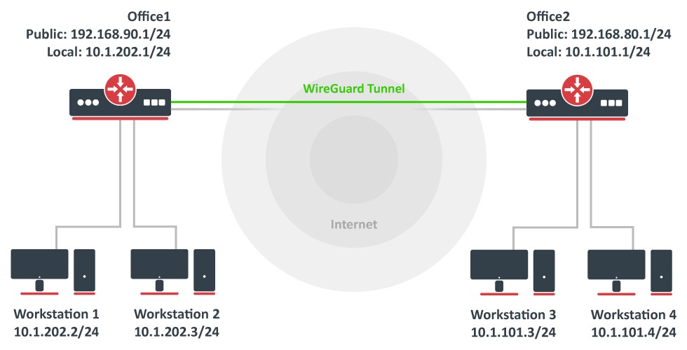
Site to Site WireGuard tunnel
Consider setup as illustrated below. Two remote office routers are connected to the internet and office workstations are behind NAT. Each office has its own local subnet, 10.1.202.0/24 for Office1 and 10.1.101.0/24 for Office2. Both remote offices need secure tunnels to local networks behind routers.
WireGuard interface configuration
First of all, WireGuard interfaces must be configured on both sites to allow automatic private and public key generation. The command is the same for both routers:
/interface/wireguard
add listen-port=13231 name=wireguard1
|
Now when printing the interface details, both private and public keys should be visible to allow an exchange.
Any private key will never be needed on the remote side device - hence the name private.
Office1
/interface/wireguard print
Flags: X - disabled; R - running
0 R name="wireguard1" mtu=1420 listen-port=13231 private-key="yKt9NJ4e5qlaSgh48WnPCDCEkDmq+VsBTt/DDEBWfEo="
public-key="u7gYAg5tkioJDcm3hyS7pm79eADKPs/ZUGON6/fF3iI="
|
Office2
/interface/wireguard/print
Flags: X - disabled; R - running
0 R name="wireguard1" mtu=1420 listen-port=13231 private-key="KMwxqe/iXAU8Jn9dd1o5pPdHep2blGxNWm9I944/I24="
public-key="v/oIzPyFm1FPHrqhytZgsKjU7mUToQHLrW+Tb5e601M="
|
Peer configuration
Peer configuration defines who can use the WireGuard interface and what kind of traffic can be sent over it. To identify the remote peer, its public key must be specified together with the created WireGuard interface.
Office1
/interface/wireguard/peers
add allowed-address=10.1.101.0/24 endpoint-address=192.168.80.1 endpoint-port=13231 interface=wireguard1 \
public-key="v/oIzPyFm1FPHrqhytZgsKjU7mUToQHLrW+Tb5e601M="
|
Office2
/interface/wireguard/peers
add allowed-address=10.1.202.0/24 endpoint-address=192.168.90.1 endpoint-port=13231 interface=wireguard1 \
public-key="u7gYAg5tkioJDcm3hyS7pm79eADKPs/ZUGON6/fF3iI="
|
IP and routing configuration
Lastly, IP and routing information must be configured to allow traffic to be sent over the tunnel.
Office1
/ip/address
add address=10.255.255.1/30 interface=wireguard1
/ip/route
add dst-address=10.1.101.0/24 gateway=wireguard1
|
Office2
/ip/address
add address=10.255.255.2/30 interface=wireguard1
/ip/route
add dst-address=10.1.202.0/24 gateway=wireguard1
|
Firewall considerations
The default RouterOS firewall will block the tunnel from establishing properly. The traffic should be accepted in the "input" chain before any drop rules on both sites.
Office1
/ip/firewall/filter
add action=accept chain=input dst-port=13231 protocol=udp src-address=192.168.80.1
|
Office2
/ip/firewall/filter
add action=accept chain=input dst-port=13231 protocol=udp src-address=192.168.90.1
|
Additionally, it is possible that the "forward" chain restricts the communication between the subnets as well, so such traffic should be accepted before any drop rules as well.
Office1
/ip/firewall/filter
add action=accept chain=forward dst-address=10.1.202.0/24 src-address=10.1.101.0/24
add action=accept chain=forward dst-address=10.1.101.0/24 src-address=10.1.202.0/24
|
Office2
/ip/firewall/filter
add action=accept chain=forward dst-address=10.1.101.0/24 src-address=10.1.202.0/24
add action=accept chain=forward dst-address=10.1.202.0/24 src-address=10.1.101.0/24
|